Product Support for: Starter Sets -> Big Boy (BB)
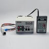
View the Product Page for the BBThe Digitrax Big Boy and Big Boy FX starter sets contained a DT200, DB100a, and an LA1 or LA2 (LocoNet Adapter). The Big Boy was shipped with one of the following mobile decoders, DH83, DH84P, DN94, DN140, DH84FX, DH83FX, DH84, DH140, or DN93FX.
Produced from 1994-1998
4 Articles Found for BB
How do I connect the BD4 to the DS54? The BD4 is a block occupancy detection device designed as an add-on device that can take advantage of the LocoNet hosting capability of the DS54 stationary decoder. It is connected in this way: The installation of a BD4 is relatively simple. Looking at the BD4, you will find a 5-point terminal block on one end and two (LED1 and DS1) 10-pin (5x2) headers on the other. There are three termination areas: a) The 5-point terminal block (left) is for the interconnection between the rail power source and the rails. b) ...
How do I connect a BD4 to a DS64? The BD4 is a block occupancy detection device designed as an add-on device that can take advantage of the LocoNet hosting capability of the DS64 stationary decoder. It is connected in this way: The installation of a BD4 is relatively simple. Looking at the BD4, you will find a 5-point terminal block on one end and two (LED1 and DS1) 10-pin (5x2) headers on the other. There are three termination areas: a) The 5-point terminal block (left) is for the interconnection between the rail power source and the rails. b) The ...
My sound decoder has a capacitor, why do I need a PX112? The capacitor that came with your Digitrax sound decoder is designed to hold up sound operation in the presence of brief power interruptions. It is not designed to keep the locomotive’s motor and lights running. Our ears are very sensitive to sound interruptions so, the capacitor on your sound decoder will prevent most of these drop outs on average quality track. Most people don’t even notice the small pauses in a locomotive’s movement and the small flashes of the lights when the track power is interrupted. If you ...
Series 4 decoders like the SDH164k1's will conform to the 10-pin wiring diagram Function pads for F1 and F2 are located on the SDH164K1 boards on opposite sides by the front headlight. Functions 3 and 4 are located on the 10-pin wire harness, with the Brown wire being the F3 negative and the Yellow wire being the F4 negative. F3 and F4 functions have a common positive connection to the solder point labeled in the middle of the board. The common LED sizes used are 3 mm and 5 mm.
