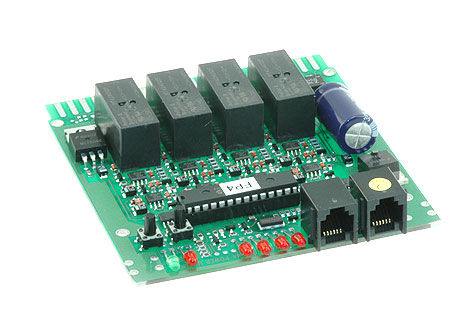
The installation instructions indicate that a PS14 be used to power the PM42.
Is it necessary that I cut the wire from the PS14 so that is can be attached it to the 44-pin connector, or is there a male adapter available for the connection?
Yes, currently you will need to cut the wire, strip the ends and solder them to the edge connector of the PM42. Please see the related articles below.
Which lead from the PS14 is to be soldered to terminal 3 on the 44-pin connector and which is to be soldered to terminal C?
The PM42 documentation states that the inputs are from an "AC or DC 12-18V Power Supply", so it doesn't matter which is connected to which. If powering more than one PM42, observe polarity is matched from one PM42 to the next.
Because of timing issues, it is also strongly recommended that the PM42 has its own exclusive power supply.
This power supply must not be part of the power loop for the booster, thus the need for the PS14 power supply or equivalent.