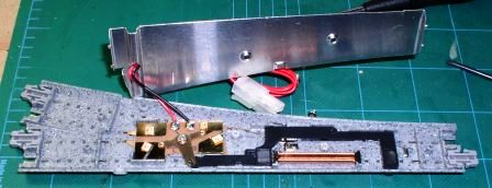
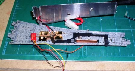
The DS51K1 is designed specifically for Kato N-Scale turnouts. Kato manufactures both a #4 and #6 turnout; one DS51K1 will control one Kato turnout solenoid. In cases where there are two turnouts in a crossover track arrangement, you must use two DS51K1s, each assigned to the same address.
Installation of the four decoder wires requires soldering skills. And, just to make things interesting, Kato uses the colors of black and red for their turnout control wires, while Digitrax uses black and red for the power and data bus. You will make four connections, two connected to the turnout motor and two to your power and data bus.
1. Turn off track power.
2. Connect the orange and gray wires from the DS51K1 to the turnout motor.
3. Connect the red and black wires from the DS51K1 to the track or power bus.
As with much else in life, there is an easy way and a not so easy way. Of course, the not-so-easy way also has something to recommend it.
The Easy Way
On the bottom of the #4 turnout is a modular connection point.
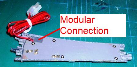
In this approach, you simply cut the red/black modular wire that came with the turnout and solder the orange and gray wires from the DS51K1 to this wire pair. The black and red wires from the decoder are connected to the power bus. The yellow wire is used to program the decoder address and then is folded away.
The not-so-easy way
With this approach, you install the DS51K1 inside the track, which requires that you open the bottom of the turnout. Units from earlier production of the #4's simply need a No. 1 Phillips driver; current production requires a No. 1 Torx driver, usually available at hardware stores.
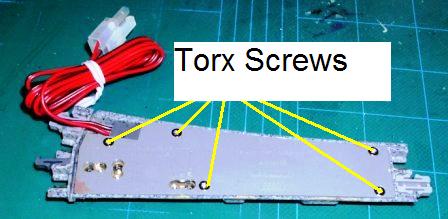
Inside the #4
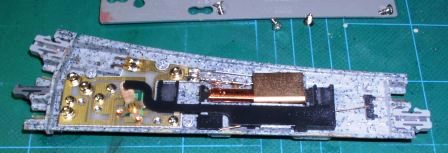
On the upper left is the modular connection point; the shiny copper wires in the center are the two solenoids of the turnout mechanism. The orange and gray wires are connected to the solenoid; the easiest way appears to be connecting to the two pins of the turnout that the modular plug fits onto. If the turnout throws in the opposite direction ("t" or "c") from what you desire, the orange and gray connections should be swapped. The decoder black and red wires are then connected to rail power connections inside the turnout; the Kato terminal joiners may also be used. You will find that an ohmmeter will help you identify the rail power connections if you choose to solder internally.
The decoder is then fitted into a vacant space (usually the small space where the modular connection is located); it's a snug fit:
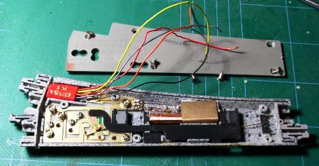
Locating the DS51K1 in this space still leaves the yellow wire open to reprogram the address of the decoder.
The #6 turnouts have two Phillips-type screws and, fortunately, there's more space in the #6 turnout:
