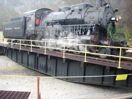
Connecting a turntable to a DCC model railroad is easy.
Each of the tracks approaching the rotating turntable bridge should be wired with the same orientation. The power feeds through a pair of conductive rings to a pair of electrically conductive brushes that are wired to the rails of the turntable bridge. DCC power is fed to the turntable bridge through an AR1 Autoreverser; when a locomotive enters or leaves the turntable bridge, the AR1 properly orients the DCC signal.
Some turntable designs have a "split-ring" electrical pickup, where the two electrical contacts that power the two rails on the turntable itself are both completed at the center of the table. As the table turns, these two electrical contacts press against the two portions of the split-ring. With DCC, this arrangement will not produce acceptable results because of the abrupt change of electrical phase when the contacts pass over to the other half of the ring. Modern turntables use a continuous pickup, where the center contact of the turntable provides half of the electrical circuit and the outer rail of the turntable provides the other half. This arrangement means a continuous flow of track power and DCC signal.
The motor which turns the table bridge is connected to a locomotive decoder and operated by a throttle in the same way as a locomotive. Because you want the turntable to operate slowly, you can change the CV's 2, 5, & 6 of the turntable motor decoder to a lower speed value. Since this decoder must have an address, assign one which is easy to remember.
Turntable indexing, which automatically aligns the turntable to a specific track is a more advanced application.