Q: How can the DS54 be configured to control a Flashing Crossing Signal?
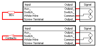
A: The elements necessary to create a simple function flashing/blinking crossing signal are: a block occupancy detection (trigger) device, an electronic flashing/blinking circuit (DS54) and a crossing signal. The DS54 can accommodate two different types of triggering devices: Digitrax block occupancy devices (BD1 and BD4) and third party block occupancy devices (such as magnets and reed contacts). The following drawings indicate how to connect the two different types of triggering devices, along with the crossing signal, to the DS54. The upper drawing is for the BD1 or BD4 and the lower drawing is for third part block occupancy devices that make use of isolated contacts. 
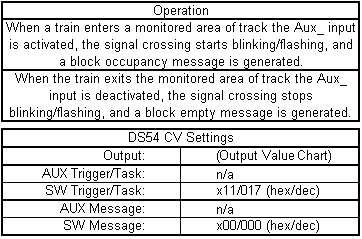
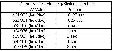
DS54 - Flashing Railroad Signal CrossingThe following two charts indicate operating criteria and CV settings. 

Note 1: There is more than one location where the switch input can be found: the red wire on the output connector and the SWx on the input connector. Note 2: There is more than one location where the ground connection can be found: the black aux power input wire and the screw terminal beside the local input connector.