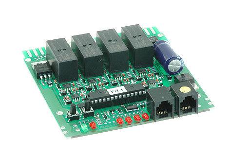
How can I remotely monitor the input and output status of a section of the PM42 that is configured to act as a circuit breaker at a remote location?
The final output stage, of each section, of the PM4 or PM42 is a DPDT relay.
The contacts of this relay act in a similar fashion as the contacts of a DPDT toggle switch.
These inputs and outputs can be monitored in a variety of ways.
Three common monitoring devices are a LED (with appropriate resistor), a lamp (of the appropriate voltage), or an optical coupler (with appropriate resistor).
The following diagram is a conceptual configuration for the monitoring of the input and both outputs of a PM4 or PM42 relay that is programmed for circuit breaker operation.
When the circuit breaker is in the normal state rail power passes from rail input to rail output normal.
When the circuit breaker is tripped rail passes from rail input to rail output reverse.
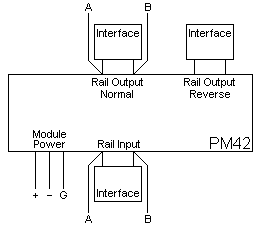
The chart listed below indicates the edge connector pins associated with each monitored section of a PM4 or PM42.

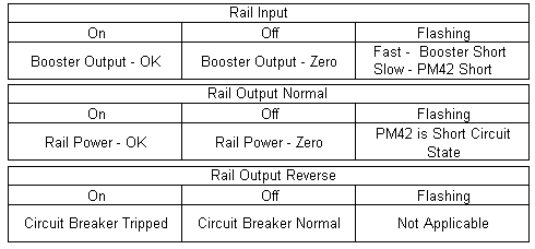
The following charts indicate the condition of the input/output in relation to the activity of the input/output interface circuitry activity.
The default configuration and most common utilization of each section of the PM4 or PM42 are as a circuit breaker.
Application Note
Note: Each relay of a PM4 or PM42 can be individually controlled to respond automatically (default state) when a short occurs or to be latched manually, via computer software, into one position (normal) or the other positions (reverse).
One application for this action is to manually disconnect and isolated section of track for the storage of DC analog engines.
A second application for this action is to select a type of activity of an isolated section of track for the purpose of operation verses service mode programming.
Application #1
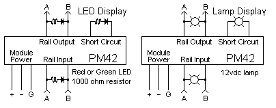
The following diagram provides the basic information for monitoring the inputs and the outputs with either a LED or a lamp.
Mixing and matching is possible.
The value of the resistor in the LED circuits may vary depending upon the desired brilliance of the LED.
Application #2
The following diagram provides the basic information for the monitoring of the inputs and outputs by an optical coupler circuit for remote audio, visual, or other third party circuitry.
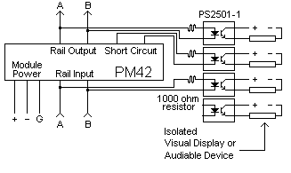
The optical coupler used in this example (PS2501-1) is just one of many optical couplers available for this type application.
The output side of the optical coupler needs to be match with the type of load being driven.
The creation of a circuit using an optical coupler is not for the electronically challenged hobbyist.