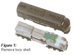
1. Carefully remove the locomotive's shell from the frame.
Notice the orientation of the shell for reinstallation.

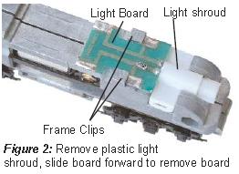
2. Carefully remove the plastic light shroud by gently prying up the tabs on either side of the frame and lifting the plastic piece off the frame.

3. Slide the factory light board forward to release it from under the clips on the locomotive frame.
Be careful not to distort the frame clips as you slide and lift the light board off the frame.
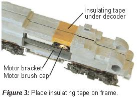
4. Place the small piece of kapton tape provided with the decoder on the loco frame, wrapping it around the sides as indicated in the figure below.
The tape should cover the side of the frame to insulate the motor clips from the frame.
Trim the tape so it does not interfere with motor brush caps.

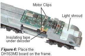
5. Align the notches in the sides of the DN163M0 decoder board over the frame clips.
(See Figure 3)
Be careful to insert the brass motor clips inside the plastic motor bracket Press down and slide the board back and under the frame clips to lock the board in place.
Be careful to keep the motor clips between the bracket and the motor brush caps on both sides of the locomotive and not bend them.
Replace the light shroud.
Please see Figure 4 (below).

6. Place the locomotive on the track, select address 03 on your throttle and apply power.
If the motor does not respond but you can control the lights, check the installation for motor short circuits.
For this installation, be sure the kapton tape is preventing contact between the frame and brass motor clips.
7. Digitrax decoders are set up with configuration variable (CV) default values so you can run your locomotive right away using address 03.
This site has instructions on setting up the CVs for customizing your locomotive's performance characteristics.
Installation Notes:
Do not exceed the decoder's 500mA total function output rating.