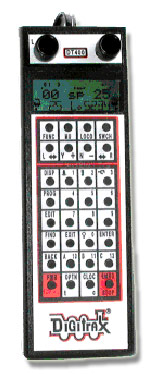
Q: I connect my DT400 to my DCS100 and it works fine, but when I add a DB150 working as a booster the DT400 stops working.
What is wrong?

A: A number of things may cause this, so you can use the diagnostic features of the DT400 to solve this problem.
Experience has proven that the most common LocoNet problem is related to pins 3 and 4.
By following this diagnostic procedure, you can narrow down to the source of the problem.
Starting with DT400 without a battery
[The throttle has no battery for this test to assure it executes a Power UP test.]
1) When plugging the DT400 without a battery into a command station (and with no UR90 or UR91 units connected on LocoNet), the normal start-up sequence is:
a) All the display segments on the DT400 will flash.
b) It will identify that it is a DT400 and show its version number.
c) There will be a short voltage flash of 8 to 14V, (depending on devices connected) on the Railsync pins 1 and 6 (blue/white wires).
d) The DT400 then very quickly turns on the display backlight briefly and re-measures the Railsync voltage and then flashes this voltage on the display.
This second voltage display will typically be about 0.5 to 1V less than the first number in step (c).
These 2 flashed voltages allow a "quality" of Railsync to be established.
The Railsync voltages are used by Boosters as "images" of the signal that they boost to the rails of their powered segment.
Within the power limits available, these run throttles and such which are connected directly to the LocoNet.
e) The DT400 then tries to Log-on to the Command Station using pins 3 and 4 of the LocoNet cable, which is the data circuit.
If data transmission is successful the display will return within a fraction of a second to the last throttle settings, with the letters "sp" in the middle of the display.
If you do not see this sequence
2) You may be able to infer the likely problem by determining the point of departure from this typical startup sequence; if a particular phase of the start-up sequence does not occur, then this may indicate the problem area.
3) The most common problem for the LocoNet data connection is failure to log on properly.
This will be indicated by an inability to log on the previous locomotives, or inability to change the locomotive address selection.
LocoNet Problems Pins 3 & 4
Most LocoNet data problems are due to pin 3 and 4 (typically red and green wires) of the LocoNet wiring not being not connected together at some point in the whole system.
If you connect a UR90/91 or even a jumper plug with pins 3 and 4 shorted, this problem will be resolved in many cases.
For the technically inclined, the reason this may be an issue on some layouts is that the LocoNet wiring on most LocoNet devices does not short pins 3 & 4 in the 6wire cable, but bridges them through, to allow the backbone wiring of LocoNet to be used in different ways.
DT400 and Cable Pin Reversal
A properly wired DT400 only connects to LocoNet data on the Green wire.
The DCS100 front LocoNet pins also connect to LocoNet data on the same pin location, so when you plug the DT400 directly into a DCS100 running as Command Station [and no other LocoNet wiring connections disturb the voltages] the DT400 will work correctly and log-on OK.
If you now connect the DT400 at a different point on LocoNet, and there is a cable pin-reversal and pins 3 & 4 are not bridged, then the DT400 will be trying to talk to the DCS100 or similar Command Station on the wrong data pin, so it will never get a reply, and hence appear to "fail" to work.
(Note that this problem may appear to "come and go" as you plug into different jacks, and this may be hard to explain or resolve).
Voltages on Pins 3 & 4
4) It is also possible to measure the voltages on the LocoNet pins 3 & 4 (red/green wires) on a test plug with a DC voltmeter. With a DT400 connected, this voltage will typically be in the range of +8 to +10V with respect to the ground pins 2 & 5 (black/yellow wires).
Normal Operations
5) If you simply put a battery into a disconnected DT400, the unit will flash the battery voltage and then go to "IDLE" in the display because it is not connected to LocoNet.
In this situation, the LocoNet data pins are at zero volts for greater than about 1/8 sec, telling theDT400 to go to the power saving 'idle' mode.
This is useful for extending battery life with plugged-in wireless throttles when the DCS100 or Command Station goes to the "sleep" mode, i.e. you do not need to remove the batteries in most cases to get zero sleeping drain.
Notes: Adding UR91/UR90 units to the network change the DT400 display sequence noted above.
The DT300 has the same display sequencing as the DT400.
While the LT1 can conveniently give LED indications of the voltages on the LocoNet wires, we do not recommend leaving this connected to a running LocoNet since the load caused by the LT1 is relatively high for continuous running.