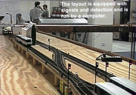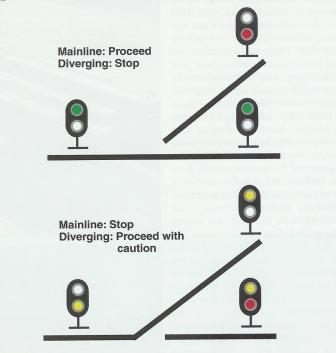
The layout uses twenty-eight turnouts on the mainline and an additional eleven turnouts in the yard. Each turnout is powered by a Tortoise slow motion turnout motor. Each of the twenty-eight mainline turnouts has three dwarf signals associated with it. The aspects of the signals are shown below.

The indications of the signals are: Green = Proceed Yellow = Proceed with caution Red = Stop Each signal has one head with two LEDs. There are also thirty-eight mainline block signals (red/green) that are controlled by heavy duty single pole double throw relays. This makes a total of 122 signals. Since one LED is always lit in each signal, the total draw on power supply #3 which is used for the signals is an astonishing 3.5 amps. This shows how 122 small things can add up to a very big thing. The thirty-one switch motors are controlled by nine DS54 stationary decoders with a total of thirty-six function cells. Some of the turnouts form crossovers and are ganged together and controlled by a single function cell. Another twelve DS54s are used to control the thirty-eight SPDT relays that operate the block signals. Block occupancy detection on the mainline is controlled by eight BD8 block detection units with each unit containing eight block sensors. Three additional BD1 block detectors report the track status for the reversing loop. The block detectors feed back to the computer through the sensor inputs of the stationary decoders via LocoNet. Even when using manual control, the turnouts, detection and signal logic are all controlled by the computer using WinLok. Because of this, the DS54s are programmed for turnout control, positive feedback and signal control only. There are no local routes used by the DS54s and there are no routes in the DCS100 so, the DS54s do not execute any cascaded routes. The entire layout is built to heavy duty commercial standards and because of the service involved with this layout, it is not overkill. The layout has been designed for long life by operating every piece of equipment at much less than full power, with a view to the maximum reliability.

Information orignally printed in The Digitrax Big Book of DCC
Part 4 of 5